

The Star-Delta circuit is one of the most common circuits used to start a motor as it deals with the high starting current of the motor. It can be confusing to wire up the circuit from just the circuit diagram. Here we have mapped them out to the real components and provide a step by step guide to wiring a simple star-delta circuit.

Video Transcript
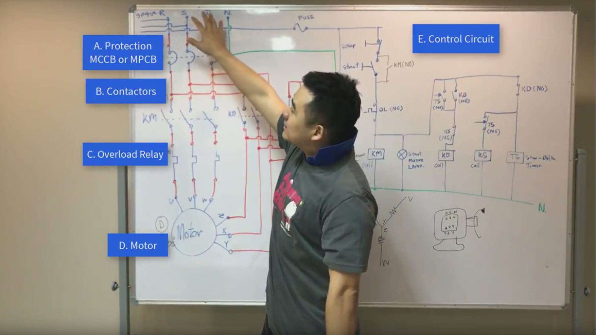
Hi, Welcome to the Beginner’s Guide to Wiring a Star-Delta Circuit. First of all, we will outline the circuit layout and show you the components. I’ll come and stand over here. This is the complete start-delta circuit that we drew up. Now Let’s see the circuit; the supply of the circuit is, of course, the 3 phase supply.
The first component we will need is a protection device, either a Molded Case Circuit Breakers MCCB or a Motor Protection Circuit Breaker. Next is the contactors, an overload relay, and finally the control circuit
We will next map out the actual equipment to the circuit so that you can see things clearly

Protection; Molded Case Circuit Breakers or a Motor Protection Circuit Breakers
This is a Motor Protection Circuit breaker. It is a circuit breaker that is designed especially for the motor starting application. The input power R S T symbol feed into here accordingly, and come out here. From here the cable goes to the contactors. Here is the start… and the stop button. It’s similar to a normal circuit breaker. This one has a special overload feature that can also be used to protect from over current

Wiring the Contactors KM, KD, and KS
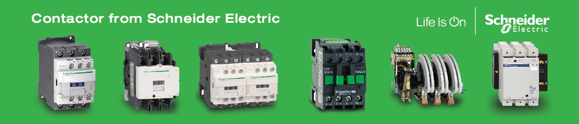
Ok next… When you have completed the connection to the MPCB. Take a magnetic contactor. This one is from Schneider Electric. And connect them (MPCB and Contactor) together. It’s pretty forward the connection line up R S T
From the diagram, the symbol is the KM
Now we bring out the second contactor in the diagram it’s the KD, which is the delta contactor. it’s from a different brand since all of the equipment we buy ourselves
It would be nice to have a sponsor from a manufacturer so what we don’t have to buy the equipment and they get their products featured in our content
Ok, You wire the connection from the Circuit Breaker to the second contactor.
The Lovato contactator, if you can see it, is written L1, L2, L 3 and matches up to our R S T symbol. Here is the Lovato contactor’s auxiliary contact. We are not using it here. So from here (T1), here (T2), here (T3) to here (L1), here (L2), and here (L3).
Here I’ll lift it up so that you can see it clearer
Next contactor is the KS which is the Star contactor. We don’t have it here but you can just wire it and there will be 3 of them.

Attaching the Overload Relay
When you have connected up the 3 contactors take the overload relay. Here is one from Schneider and here is one from Lovato Electric. You only need one.
Connect the overload relay like so… And screw in the connection to fix them together.
The cable out from the overload relay you will connect to the motor according to the circuit. The R S T map to U V W. The Star and Delta contactors do not need to have an overload relay; you only need one overload relay per set of a Star-Delta
If you are using, for example, Lovato contactor as the main contactor; you will attach the overload relay to it. And use Schneider’s contactor as the delta or start accordingly. They do not need to have an overload relay.

Can the contactors in a star-delta set be form different brands?
Now the question is “In the real situation, can you use different brands in the same star-delta set?”
And the answer is “Yes, you can” It doesn’t matter. Not at all.
Although if you are pairing up the contactor to the overload relay, it should be the same brand. This is because the manufacturers design the terminal connection to match only their own product set. If you try to connect a Lovato’s overload relay to that of Schneider’s then it doesn’t fit. That’s all.

This concludes Part 1; the power side of the circuit. We will talk about the control circuit in the next episode. Part 2 will complete our series “The Beginner’s guide to wiring a star-delta circuit”
If you like the video please give it a thumbs up. Any questions, please leave a comment. And Subscribe to not miss our upcoming video. Thank you and stay tuned for part 2
The Beginner’s Guide to Wiring a Star-Delta Circuit (Part 2)
Hi, Welcome back to the article “The Beginner’s Guide to Wiring a Star-Delta Circuit”. This is the second part of the series and we will be talking about the control circuit. Let’s take a look.

Let’s start off by giving a short overview of the equipment. In this circuit, there are Push Buttons and Pilot lamps and we are using Schneider Electric’s XB5. This green Push Button is used as a START button and we will use it to start the motor. It is a normally open push button. You can see the symbol NO at the bottom. The red STOP button is a normally-closed push button and you can see from the bottom here labeled NC.

Now on to the Pilot Lamp. The red lamp, in this case, is used to show the motor overload status. The pilot lamps are LED light and are nice and bright. The green pilot lamp will be on when the motor is running and off when the motor stops. To START the motor we press the green push button, to STOP the motor then press the red push button.

On to other equipment, you will need cables, the right cable for this 9A contactor is recommended as an AWG from 10 to 18 which is approximately 2.5 square millimeters.

After that, you will need 3 contactors. The first one is the main contactor labeled KM. This one is from Lovato Electric and you will need one with a Normally-Open auxiliary contact. The second one is the Delta Contactor labeled KD. This one you will need the auxiliary contact to have both NO and NC. The third is the Star contactor labeled KS. It will also need the auxiliary contact to have both NO and NC. The three of them can be of the same size. The main one will need to have an overload relay connected to it.

KM Contactor from Lovato Electric

Delta Contactor labeled KD

Star contactor labeled KS

Overload relay
Lastly, you will need a Star-Delta timer, which will be used to sequence the contactors. We don’t recommend using normal timers. Since it is better to have a delay function. Let’s take a look at the specific function of a Timer that is designed for the Star-Delta application.

You can see more information from the diagram on the side of the timer. This Timer is from Lovato Electric TM ST series. As you supply the current from A1 to A2 the Star Contactor will start, then there will be a transition delay, we can set the value of this. Then the Delta contactor will start. The transition function prevents both the star and delta contractor from working at the same time. Now, if you were to use a normal timer there will be no transition delay the timer will immediately switch the contactor from Star to Delta. This will work but there is a chance that both star and delta contactors will be working at the same time and may cause some problems.

Let’s see how we can set up the timer. The top dial is the range and is like a multiplier.

The second dial is the time period that the star contactor will be ON.

The last setting is the period to delay between Star and Delta.

For example, if we set this to 10 seconds, you can see the arrow pointing here, then set this time to 3, this will means that the Star contactor will be on for 30 seconds.

The delay here has a minimum of 20 milliseconds. To recap, you set the Star period then the transition time. The maximum transition time you can set for this timer is 300 milliseconds.
Get a Quote for Motor Control Equipment from us
On to wiring the timer to the delta and star contactors. The easiest way to show is from Line to Neutral. 220V AC supply in. It connects to A1. The A2 then connect to the neutral. Then we will connect the timer to the contactor’s auxiliary contact. There’s 18 here and 28 here. 18 is connected to the star which is this one here. Into the coil that takes 220V. On the contactor it will label A1. A2 from the contactor goes to the Neutral completing the circuit.

The other contact 28 is connected to Delta A1 and the A2 also goes to the neutral. There are 3 connections to the neutral, these three here. From the Line there should only be 1 connection; this one. Now, the circuit is complete and we can start the motor using this Star-Delta configuration!
If you have any questions or comments then please feel free to ask. Press like to show support for our production team. Subscribe as to not miss our upcoming videos. That’s it for today, thank you and see you again soon.